 (ES)")
")


INSTALLATION


|
Installation Instructions for the KEC Residential Unit Authorized KVAR dealers and distributors and sales agents shall not be responsible for any damages, personal or property, resulting from the installation of this product in a manner which deviates from the instructions specified herein.
|
|
|
KEC 100 Amp & 200 Amp - Installation Instructions
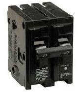
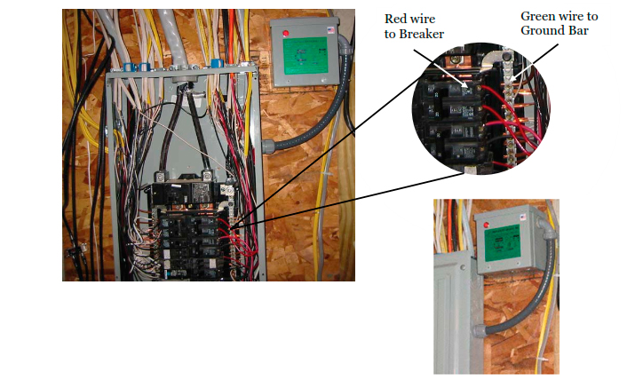
1. Make visual check on breaker sizes & location Locate an existing or purchase a new full size double pole 240 volt 20 amp or 30 amp breaker designed for your panel. NOTE: these take up 2” of space. • Position that breaker directly below main breaker using the first two bus line slots on either side of breaker panel. It should be installed in the top slot on the left or right side of the panel. NOTE: If the main power comes into the panel from the bottom, then the “top” of the panel is actually the bottom and the 20/30amp breaker would be the 1st breaker on the bottom. • If there is no double pole 20 amp or 30 amp breaker available in the panel, then one will have to be added (not included.) |
 |
|
3. Locate desired location & mount unit (left, right, top or bottom side of panel, nearest the knock out and breaker you will be using) 6. Setting KVAR unit into operation |
|
 |
|
|
WHERE TO INSTALL THE KVAR UNIT IN RESIDENTIAL HOME APPLICATIONS AND SETTINGS:
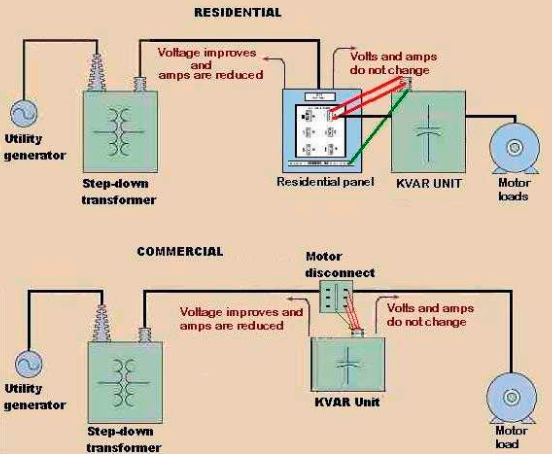
Installation in a residential home is simple as compared to installations made in industrial and commercial situations. To maximize results, the KVAR is connected to the upper most switch in the residential panel box. WHERE TO INSTALL THE KVAR UNITS IN COMMERCIAL & INDUSTRIAL APPLICATIONS AND SETTINGS: Theoretically and technically speaking, when capacitors are installed between the transformer and the load and not only at whatever other points (e.g. A, B or C), unity power factor is achieved. The utility company will perceive the power system as having a unity power factor no matter where the power factor correction capacitors are located on the distribution line as long as they are sized correctly. This is Power Factor Correction. Since KVAR Units are energy generators, the most efficient place to install them is directly at the motor where energy is consumed where the units will supply the kVAR reactive current component to the load because the KVAR unit is able to store reactive energy in its magnetic field when it charges up, and releases it when it discharges. The generator (or transformer) must still supply the load’s KW requirements, but the reactive current component is now supplied by the KVAR unit and not the generator of the utility company. 1 |
|
 |
|
|
As uniquely distinct from all the other electrical capacitors, the KVAR does not only do power factor correction and create a system-wide surge protection facility. The KVAR primarily functions as a Power Optimization Technology. Optimum efficiency and economics is achieved when the KVAR unit is installed as close to the load as possible because by doing this, the total line current to the load is reduced and therefore the total losses in the line conductor in the forms of heat or noise is reduced and the voltage drop in the line is decreased. The other electrical capacitors do not provide this optimization value which the KVAR does. The energy “contained” in the KVAR current component is transferred back and forth between the KVAR unit and the motor two times for every voltage (i.e. at 120 times a second). This FREE reactive energy (kVAR) produced by the KVAR is never consumed by either the KVAR unit or the motor (in contrast to the KW energy which performs real work and is totally consumed) is only “borrowed” half of the time by the KVAR unit and half of the time by the motor. The energy is used to charge the AC electric field of the KVAR unit and to energize and create the AC magnetic fields contained in the motor windings. In short, the capacitance in the KVAR unit and the inductance in the motor’s windings “slinky” this reactive energy back and forth 120 times a second, each supplying the needs of the others.
|
|


